


RGB Mods
G1 Mod Kit (Fully Assembled)
G1 Mod Kit (Fully Assembled)
Couldn't load pickup availability
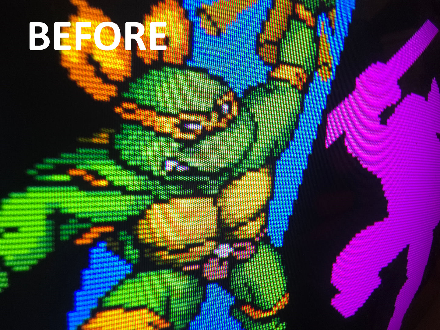
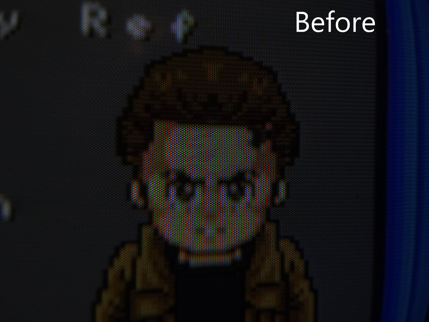
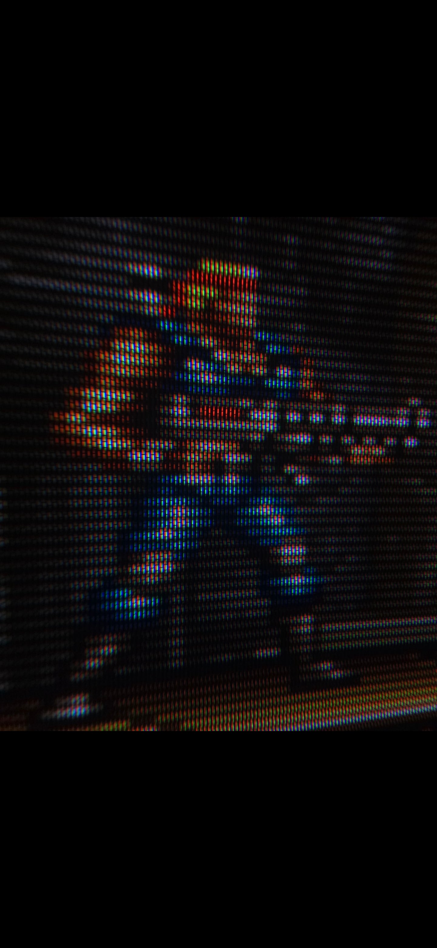
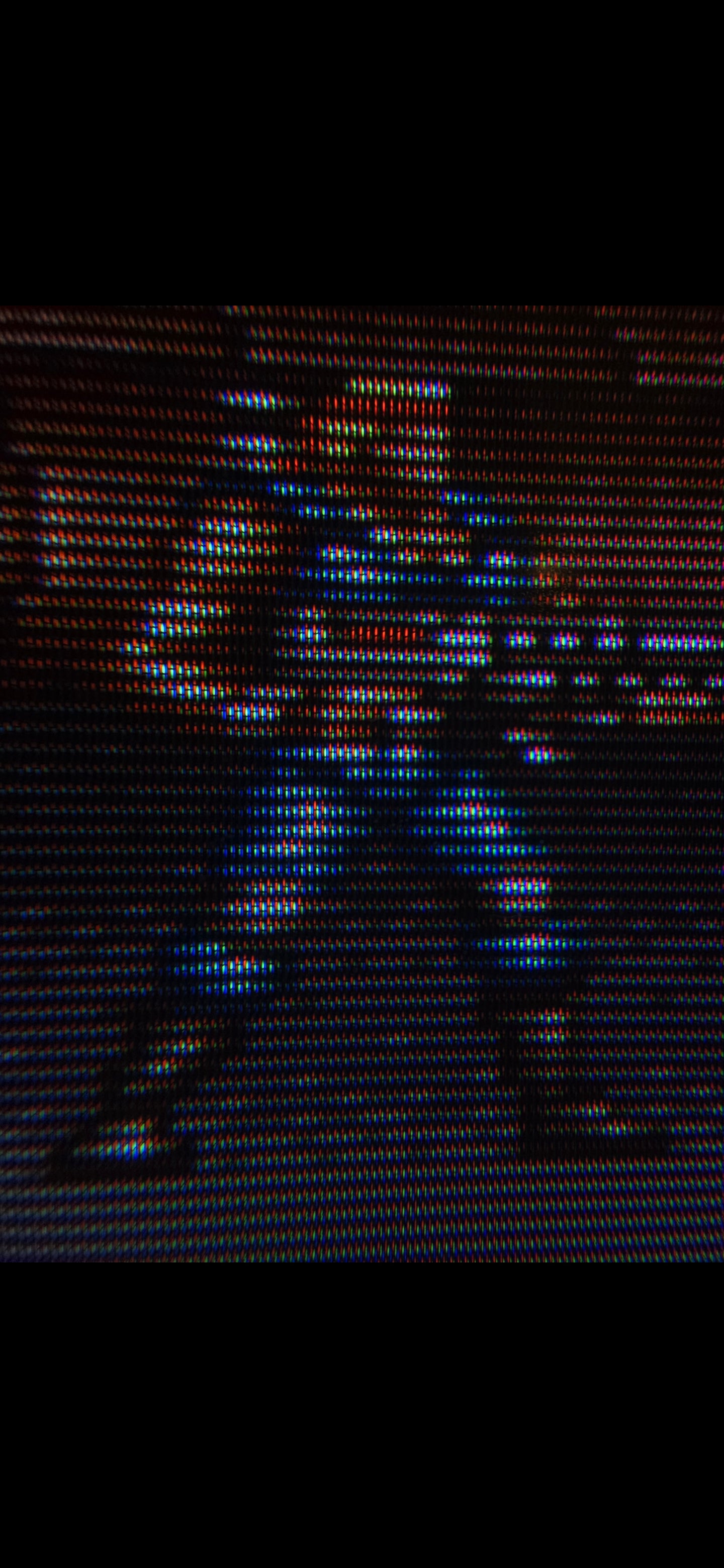
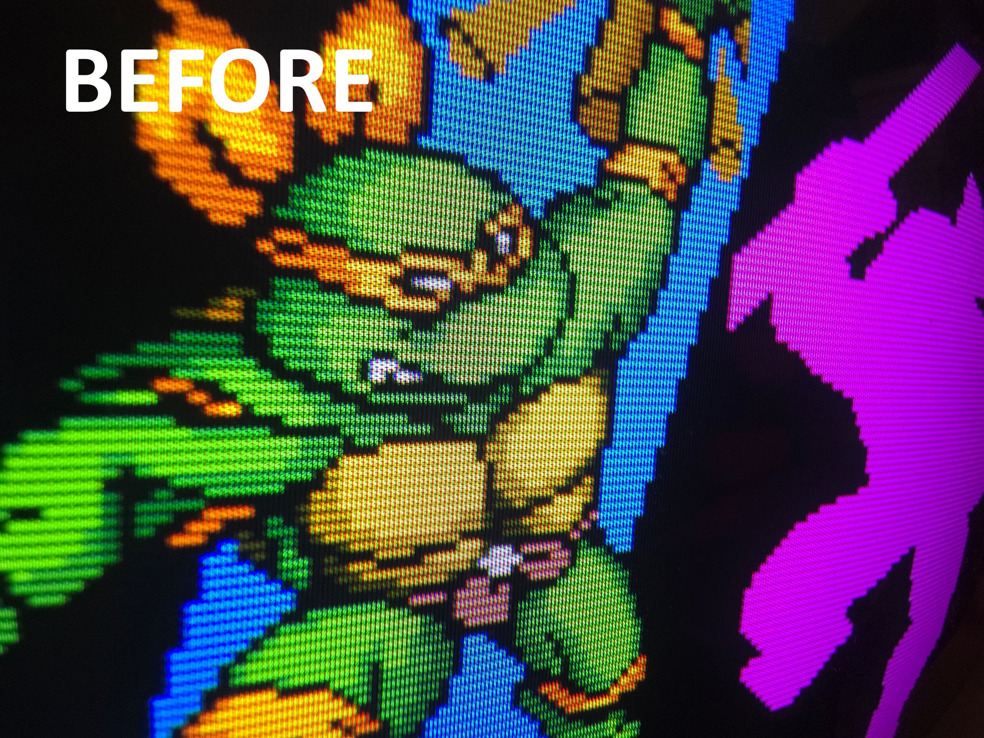
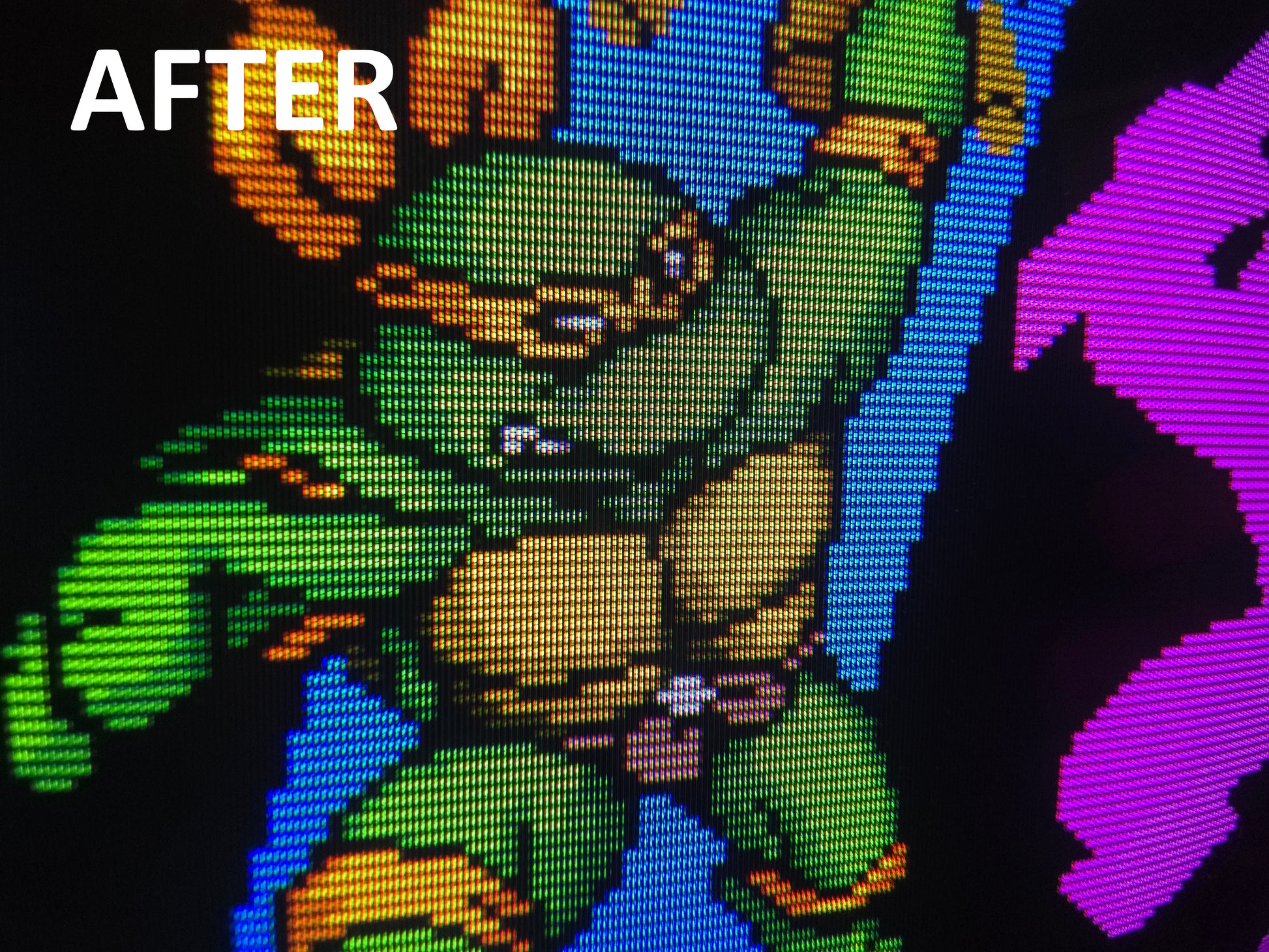
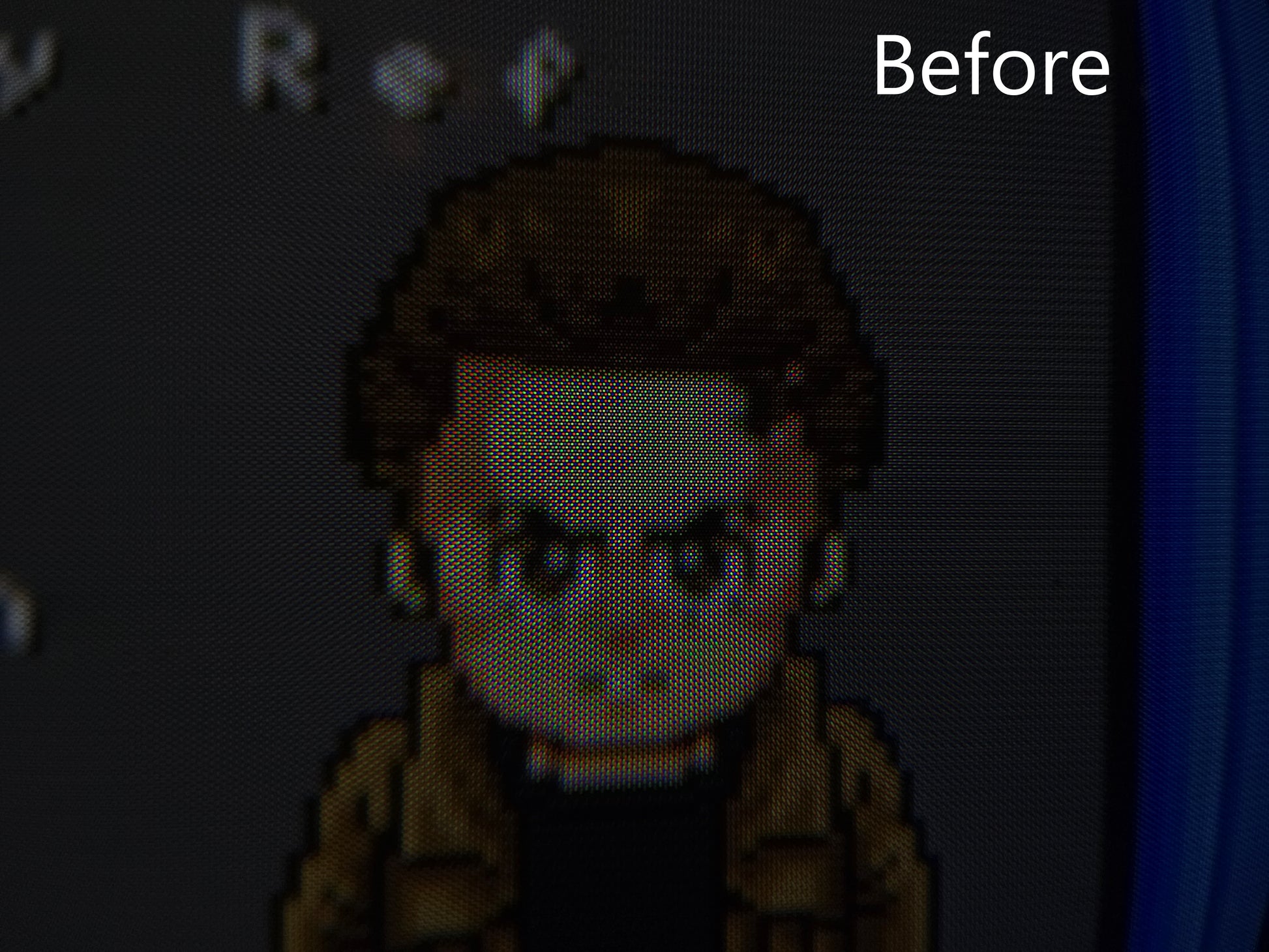
Gain even more control over your tv/monitors focus!
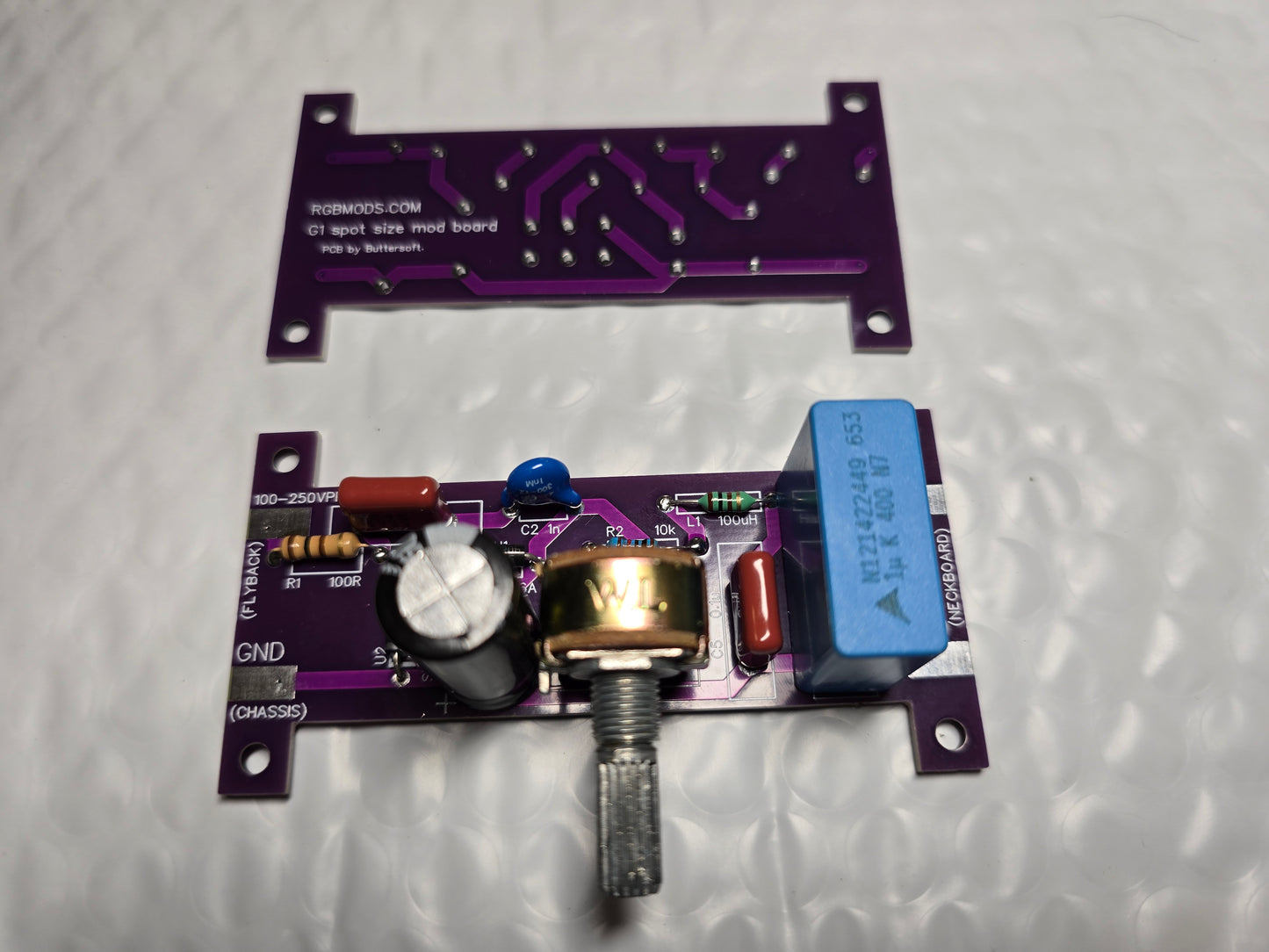
Now we have custom pcb's created for the G1 Mod kit! The board looks a little bit different than the tutorial video now, but it should be obvious where things go! Thanks for the help Buttersoft!
How to install video:
https://youtu.be/USRP-l8v0b4
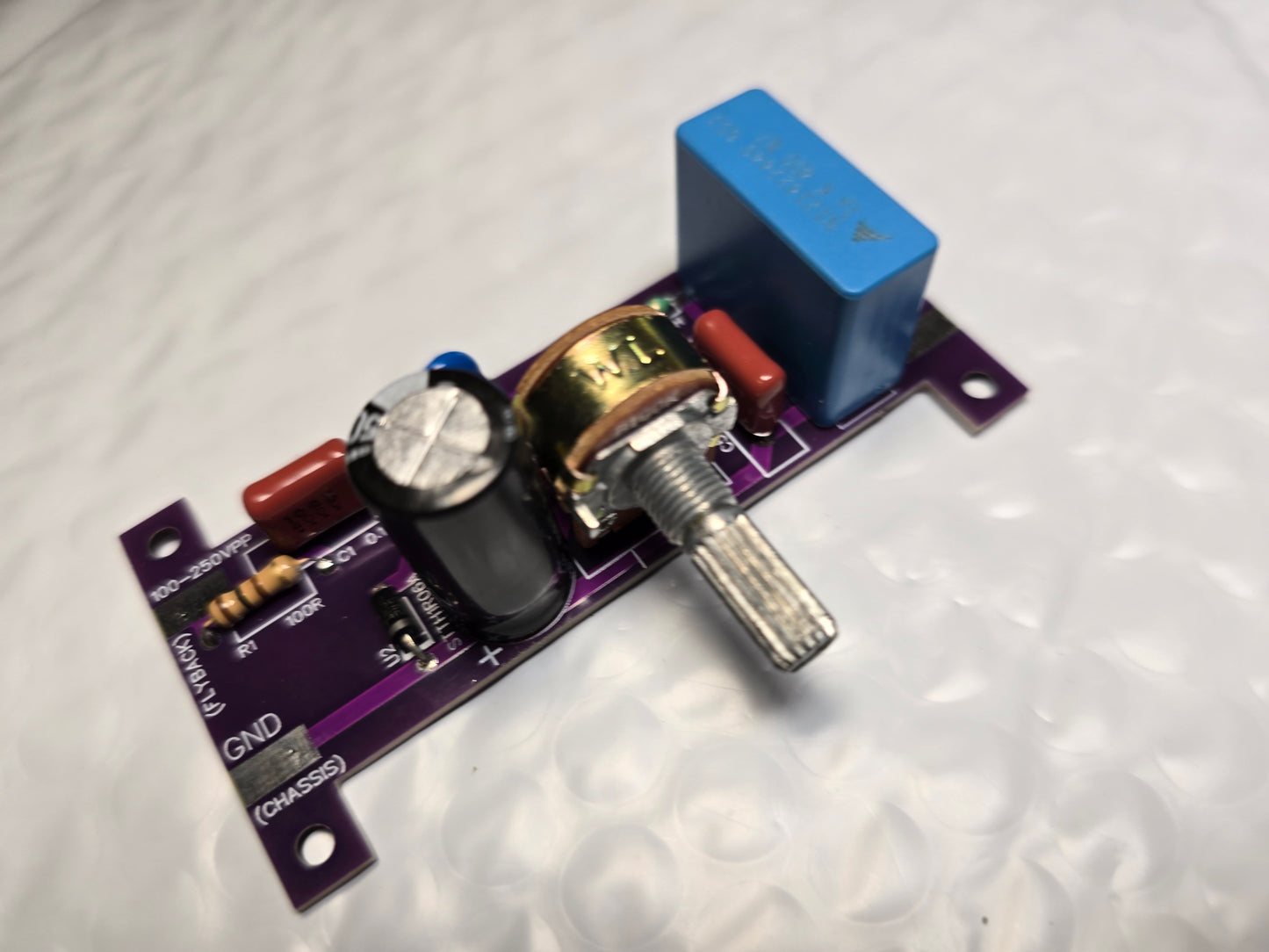
This includes the board with everything already soldered correctly in place. I recommend using 18awg wire or lower when hooking it up. On one end of the board you go to the ground and the negative source on the flyback (between -100 and -250v), on the other end of the board you go to ground and the G1 pin(s) on the neckboard.
You will need to isolate the G1 pin(s) on the neckboard from everything else. This means either scraping away the trace, or clipping the leg of component so there is no continuity between the G1 pin(s) and anything else.
It's as easy as that, improve your crt sharpness in a matter of minutes!
Some crt's have more than one G1 pin on the neckboard. I've seen this on Sony's more than anything else. In those cases, you would have to isolate each of the G1's, and run your wire to each of the pins on the neckboard. I've seen cases of two G1 pins, and other cases of three G1 pins. They may be each labeled as G1, or maybe G1-1, G1-2. In any case you need to run a wire to each of them. You can run separate wires from the pad on the mod board, or you can run one wire, and split it. Either way works!
Once everything is all setup, and you turn on your tv for the first time you will likely need to turn the G2 pot on the flyback up to get your screen back to where it was. You will find a balance of turning G2 pot up, and G1 pot on the board to where you're happy. If you turn the G1 pot all the way up you will find the electron beam the most focused, but that's not necessarily what always looks best. Play around with it and see what you like.
Feel free to reach out if you need any help, and I'll do my best!
If you're not using an oscilloscope to locate which flyback pin you use, you do not want to use the ground pin, or the pin which connects to the Horizontal Output Transistor. It would be wise to review the service manual of the crt you're looking at to avoid using the Horizontal Output Transistor connected flyback pin as a "test point", because it can output higher voltage than the G1 board can tolerate.
It's normal for the potentiometer on the board to feel warm!
Everything on this board was sourced from legitimate places, Mouser, Digikey etc. using the highest quality pieces.
Special thanks to Luke Simon for all the help you've given in creating the G1 Mod.
Here's another tutorial which may help in the installation process:
https://drive.google.com/file/d/1JnT7qBUdbVkzPTlVRB5mot-R5UvbFSSe/view
Credit to DreamCRT & Dave Astur from Telegram #Teles de Tubo for the Google Drive tutorial. Thank you!!
Share